Integrated Distribution Voltage Management System with Conservation Voltage Reduction (CVR) Functionality
CVR Smart Grid Project, Contributions from Natural Resources Canada (NRCan) & Ontario Ministry of Energy – Smart Grid Fund (SGF)
Primary Author:
Jacob Weninger, EIT
Entegrus – System Planning
Secondary Author:
Trevor L. Grant, M. Eng., CEO
Power Solution Resources Inc.
Entegrus serves 17 urban communities in Southwestern Ontario, scattered through rural areas extending over 150 Km end to end. This geographical dispersed territory presents challenges, including voltage visibility, voltage management, and response time to diagnose and resolve system issues. In addition, some areas are between or at the end of areas served by Hydro One.
These issues stimulated participation in an earlier successful Ontario Smart Grid Fund (SGF) project to demonstrate a grid edge technology to support distribution voltages (120/240 V) on an end of line feeder in Erieau. Edge of Network Grid Optimization (ENGO) devices were deployed on the secondary of distribution transformers to control the secondary voltage by fast dynamic injection of VARS (up to 10 KVARS in 1 KVAR increments), under local control. Set-point and system analytics were provided by a Cloud Based Grid Edge Management System (GEMS) Platform. The GEMS Platform and ENGO devices are supplied by Varentec. The primary benefits were to flatten the voltage profile and create a tighter voltage variation band along the entire feeder, and improve feeder phase balance and power factor.
Figure 1 shows the impact of the ENGO units in Erieau.

These benefits were enhanced to address voltage visibility and management issues in the community of Thamesville which is a half hour away from Entegrus Control Center and service hub, and which is embedded within Hydro One’s service territory.
The enhancement leveraged additional value streams afforded by the grid edge technology by incorporating an upstream regulator to achieve Conservation Voltage Reduction (CVR) functionality.
Through CVR, a reduction in the supply voltage achieves a reduction in energy usage and electricity Demand, and importantly, associated reductions in Green House Gas (GHG) emissions. An Integrated Smart Grid System was designed to provide Control Room Operators with voltage visibility, voltage management and CVR functionality.
This project was co-funded by the Department of Natural Resources Canada (NRCan) Green Infrastructure Phase II SGF Program to demonstrate GHG reductions by an LDC, without active customer involvement. In addition, co-funding was provided by Ontario’s Ministry of Energy Smart Grid Fund - Deployment to achieve Voltage Management and Demand and energy reduction. These program’s objectives were well aligned with the scope of the project. The primary implementation regulatory hurdle to meet the Ontario Regulation 22/04 (safety requirements for deployment of equipment on distribution feeders) was fulfilled through the execution of the first SGF project.
The system specifications defining the Thamesville target feeder are shown in Figure 2.
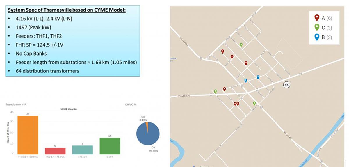
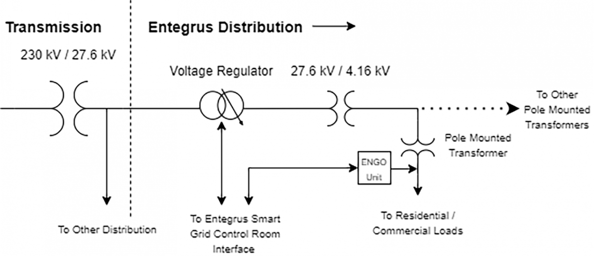
Placement of the ENGO devices were established through detailed analysis of the feeder model and historical voltage profiles. The power train architecture of the system is shown in Figure 3, wherein the new Regulator is installed upstream of the existing pad mounted 27.6 kV : 4.16 kV transformer.
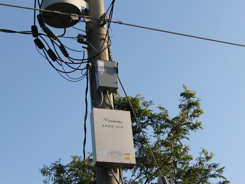
The modeling and analysis identified 11 transformers (of the 64 in the Thamesville feeder) for installation of ENGO devices, distributed on each phase. A Photo of an ENGO unit installation at Entegrus is shown in Figure 4, including an isolating Disconnect Switch.
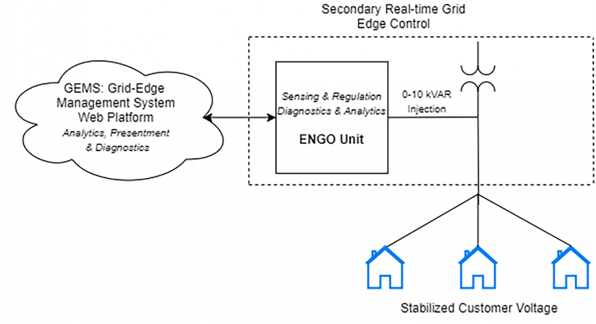
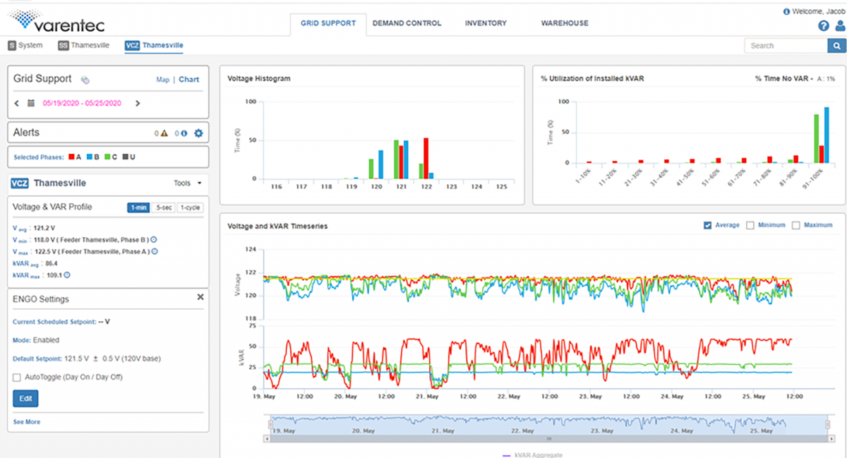
The ENGO unit provides local (edge) voltage control, with a set point derived via Varentec’s GEMS platform. Figure 5 shows the basic interfacing structure, wherein the ENGO unit provides local diagnostics of the hardware and communications, and the GEMS Platform provides system analytics, diagnostics and presentment. Figure 6 shows a sample of a GEMS Dashboard showing the Thamesville feeder status and data (ENGO settings, Voltage and VAR Profile, Voltage Histogram and VAR utilization).
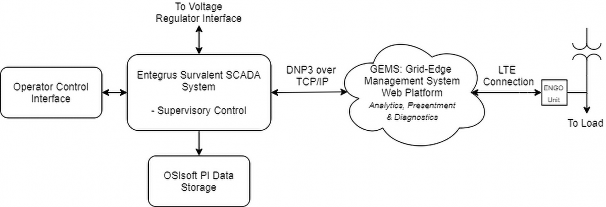
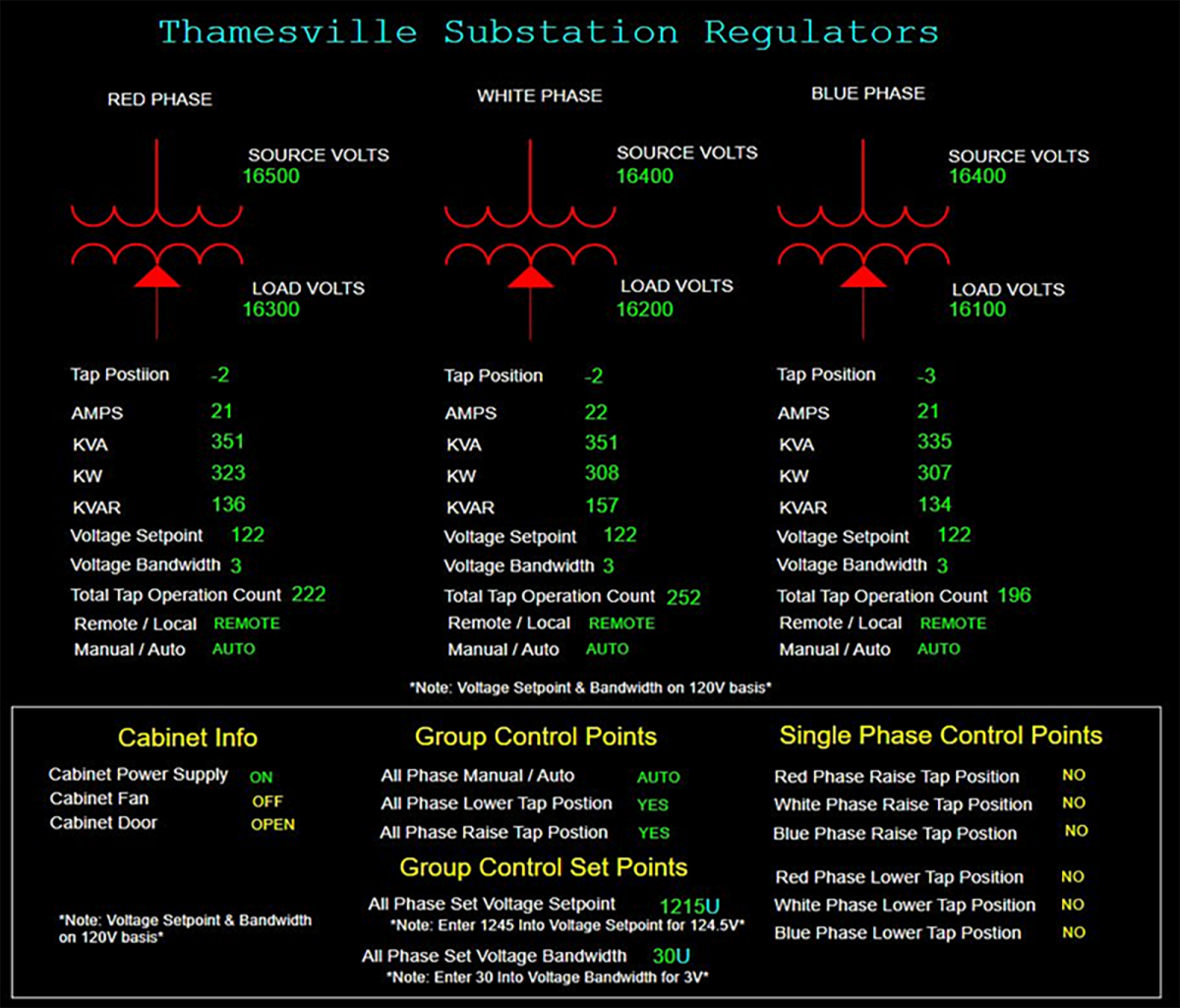
The architecture of the Smart Grid System shown in Figure 7 integrates system hardware, communications with Varentec’s GEMS Platform and the regulator controls, and programming of Entegrus’ Survalent SCADA system for data acquisition and storage, set-point control, and visualization. Figure 8 shows an example of the Operator Control and Visualization Dashboard for the Regulator.
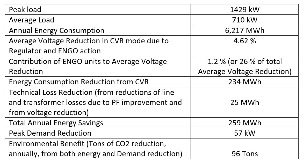
ON-OFF tests were conducted to determine the improvement (increase) in the minimum feeder voltages resulting from the ENGO controls, and thus their contribution to the voltage margin available for lowering the overall feeder voltage (via the regulator), without violating the lower CSA voltage limit. CVR tests were conducted, and through analysis, the energy savings and Demand reductions were established as a function of feeder load. These data were then utilized to estimate the annual energy savings and Demand reductions based on the historical feeder load profile. Note, the historical feeder data establishes the minimum feeder voltages as a function of feeder load. The voltage margin improvement from the ENGO units in conjunction with reduction in voltage set point of the regulator determine the potential energy savings in an optimized system (where the set-points are dynamically optimized to maximize the voltage reduction without CSA violations). As summary of the annualized results is shown in Figure 9.
